Solid-center hydraulic power chuck for short blanks, discs and repeat CNC lathe clamping.
3-Jaw Solid Hydraulic Chuck
KORRETTO 3-jaw solid hydraulic chuck is used when the workpiece does not need to pass through the spindle. It is suitable for short stock, discs, sleeves, individual blanks and rotational parts that require repeat hydraulic clamping on CNC lathes. Selection should confirm chuck size, spindle nose, drawbar stroke, solid rotary cylinder, jaw travel, clamping force, maximum speed and workpiece size.
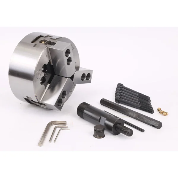
Product Overview
The 3-jaw solid hydraulic chuck is a hydraulic power chuck for external clamping of round or near-round workpieces. Because it does not use a through-hole structure, it is selected for parts that are loaded as individual blanks rather than fed through the spindle.
This page only covers the 3-jaw solid hydraulic chuck. For bar or tube work that requires through-spindle passage, use the 3-jaw hollow hydraulic chuck instead.
Key Features
| Feature | Description |
|---|---|
| Solid-center structure | Suitable for short workpieces and individual blanks that do not require through-spindle passage. |
| 3-jaw synchronized clamping | Provides external clamping for round and near-round parts. |
| Hydraulic clamping cycle | Works with a compatible solid rotary hydraulic cylinder and drawbar. |
| Batch production use | Suitable for repeat CNC turning where manual tightening is not efficient. |
| Two parameter groups | Technical data must preserve the two size groups: 15 inches and below, and 18 inches and above. |
Typical Applications
- Short blanks
- Discs and flange-type workpieces
- Sleeves and rotational parts
- CNC lathe batch turning
- Workpieces loaded one by one rather than through the spindle
Technical Data and Dimensions
The 3-jaw solid hydraulic chuck data is divided into two size groups. Keep the parameter tables separated so users can clearly identify the applicable size range.
3-Jaw Solid Hydraulic Chuck — 15 Inches and Below
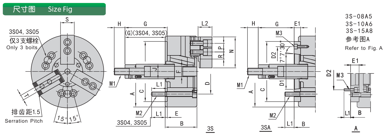
Use this drawing to check the 15 inches and below size group.
| Model | Spindle Nose | A | B | C (H6) | D | D1 | D2 | E | E1 | F | G max | G min | H | J |
|---|---|---|---|---|---|---|---|---|---|---|---|---|---|---|
| 3S-04 | 110 | 52 | 60 | 80 | 4 | 18 | 3 | 25 | 26 | |||||
| 3S-05 | 135 | 55 | 80 | 100 | 4 | 9 | -6 | 35 | 28 | |||||
| 3S-06 | A5 | 169 | 74 | 84 | 140 | 82.56 | 116 | 5 | 15 | 21 | 101.5 / 86.5 | 81.5 / 66.5 | 34 | |
| 3S-08 | A5 | 210 | 85 | 103 | 170 | 82.56 | 104.8 | 5 | 23 | 25 | 127 / 104 | 106 / 83 | 36 | 38 |
| 3S-08 | A6 | 210 | 85 | 97 | 170 | 106.38 | 150 | 5 | 17 | 25 | 127 / 110 | 106 / 89 | 36 | 38 |
| 3S-10 | A6 | 254 | 89 | 109 | 220 | 106.38 | 133.4 | 5 | 25 | 34 | 158 / 133 | 133 / 108 | 36 | 45 |
| 3S-10 | A8 | 254 | 89 | 118 | 220 | 139.72 | 190 | 5 | 18 | 34 | 158 / 140 | 133 / 115 | 36 | 45 |
| 3S-12 | A8 | 304 | 106 | 118 | 220 | 139.72 | 190 | 6 | 18 | 163 / 145 | 50 | |||
| 3S-15 | A8 | 381 | 114 | 141 | 300 | 171.4 | 6 | 33 | 104 / 71 | 69 / 36 | 55 | 60 | ||
| 3S-15 | A11 | 381 | 114 | 130 | 300 | 196.87 | 260 | 6 | 22 | 104 / 82 | 69 / 47 | 55 | 60 |
| Model | Spindle Nose | Plunger Stroke (mm) | Jaw Stroke (mm) | Max. Pull kN (kgf) | Max. Clamping kN (kgf) | Max. Speed (r/min) | Clamping Range (mm) | Moment of Inertia (kg·m²) | Weight (kg) | Matching Cylinder |
|---|---|---|---|---|---|---|---|---|---|---|
| 3S-04 | 15 | 6.9 | 8.1(830) | 22.5(2300) | 6000 | 5-110 | 0.01 | 4.1 | 80 | |
| 3S-05 | 15 | 6.9 | 8.1(830) | 25(2550) | 5500 | 14-135 | 0.02 | 6.2 | 80 | |
| 3S-06 | A5 | 20 | 9.2 | 17.9(1830) | 52.4(5350) | 5250 | 14-165 | 0.05 | 13 / 14 | 100 |
| 3S-08 | A5 | 21 | 9.7 | 25(2550) | 74.5(7600) | 4750 | 17-210 | 0.14 | 24 / 28 | 125/170 |
| 3S-08 | A6 | 21 | 9.7 | 25(2550) | 74.5(7600) | 4750 | 17-210 | 0.14 | 24 / 27 | 125/170 |
| 3S-10 | A6 | 25 | 8.8 | 28.9(2950) | 107.8(11000) | 4000 | 22-254 | 0.30 | 35 / 42 | 125/170 |
| 3S-10 | A8 | 25 | 8.8 | 28.9(2950) | 107.8(11000) | 4000 | 22-254 | 0.30 | 35 / 40 | 125/170 |
| 3S-12 | A8 | 30 | 10.5 | 41(4180) | 155.8(15900) | 3360 | 22-304 | 0.73 | 59 / 63 | 150 |
| 3S-15 | A8 | 35 | 16 | 82(8360) | 248.4(25350) | 3000 | 50-381 | 1.95 | 100 / 114 | 200 |
| 3S-15 | A11 | 35 | 16 | 82(8360) | 248.4(25350) | 3000 | 50-381 | 1.95 | 100 / 107 | 200 |
3-Jaw Solid Hydraulic Chuck — 18 Inches and Above
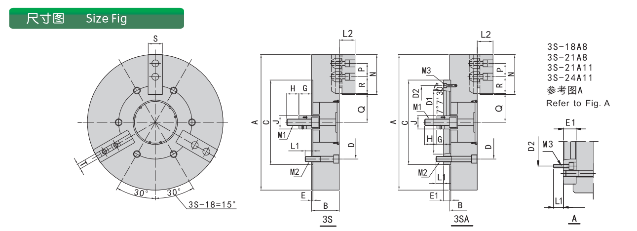
Use this drawing to check the 18 inches and above size group.
| Model | Spindle Nose | A | B | C (H6) | D1 | D2 | E | E1 | G max | G min | H | J |
|---|---|---|---|---|---|---|---|---|---|---|---|---|
| 3S-18 | A8 | 450 | 114 | 141 | 139.72 | 171.4 | 6 | 33 | 92 / 59 | 57 / 24 | ||
| 3S-18 | A11 | 450 | 114 | 130 | 196.87 | 260 | 6 | 22 | 92 / 59 | 57 / 24 | ||
| 3S-21 | A8 | 530 | 125 | 146 | 139.72 | 171.4 | 6 | 97 / 70 | 62 / 35 | 55 | 60 | |
| 3S-21 | A11 | 530 | 125 | 146 | 196.87 | 235 | 6 | 89 | 81 | 55 | 60 | |
| 3S-21 | A15 | 530 | 125 | 146 | 285.78 | 330.2 | 6 | 97 / 70 | 62 / 35 | 55 | 60 | |
| 3S-24 | A11 | 610 | 380 | 196.87 | 235 | 6 | 27 | 97 / 70 | 62 / 35 | 55 | 60 | |
| 3S-24 | A15 | 610 | 6 | 27 | 97 / 70 | 62 / 35 | 55 | 60 | ||||
| 3S-32 | A15 | 800 | 127 | 148 | 285.78 | 330.2 | 6 | 128 | 120 | |||
| 3S-40 | A15 | 1000 | 127 | 148 | 285.78 | 330.2 | 6 |
| Model | Spindle Nose | Plunger Stroke (mm) | Jaw Stroke (mm) | Max. Pull kN (kgf) | Max. Clamping kN (kgf) | Max. Speed (r/min) | Clamping Range (mm) | Moment of Inertia (kg·m²) | Weight (kg) | Matching Cylinder | Max. Pressure MPa (kgf/cm²) |
|---|---|---|---|---|---|---|---|---|---|---|---|
| 3S-18 | A8 | 248.4(25350) | 2700 | 60-450 | 2.47 | 131 / 154 | |||||
| 3S-18 | A11 | 248.4(25350) | 2700 | 60-450 | 2.47 | 131 / 138 | |||||
| 3S-21 | A8 | 1900 | 62-530 | 4.9 | 175 / 196 | ||||||
| 3S-21 | A11 | 1900 | 62-530 | 4.9 | 175 / 193 | ||||||
| 3S-21 | A15 | 35 | 16 | 82(8360) | 272.6(27800) | 1750 | 152-610 | 7 | 216 / 186 | 200 | 3.2(32) |
| 3S-24 | A11 | 272.6(27800) | 1750 | 152-610 | 7 | 216 / 234 | |||||
| 3S-24 | A15 | 35 | 16 | 82(8360) | 272.6(27800) | 1750 | 152-610 | 7 | 216 / 227 | 200 | 3.2(32) |
| 3S-32 | A15 | 1100 | 152-800 | 36.2 | 426 / 440 | ||||||
| 3S-40 | A15 | 800 | 158-1000 | 98.5 | 776 / 790 |
Selection Notes
- Use this page only for the solid-center 3-jaw hydraulic chuck.
- Do not mix the 3-jaw hollow hydraulic chuck parameters into this page.
- Confirm whether the workpiece is loaded as a short blank or needs through-spindle passage.
- Check spindle nose, drawbar stroke, cylinder thrust, jaw stroke and maximum speed.
- Use the correct parameter group based on chuck size.
FAQ
When should I choose a 3-jaw solid hydraulic chuck?
Choose a solid hydraulic chuck when the workpiece is short, loaded individually and does not need to pass through the spindle.
Is this the same as a 3-jaw hollow hydraulic chuck?
No. The hollow type has a through-hole for bar or tube passage. The solid type is used when through-spindle feeding is not required.
Why are the parameters divided into two groups?
The page keeps separate technical tables for 15 inches and below, and 18 inches and above, because larger chuck sizes may use different dimension and performance data.
What cylinder should be used with this chuck?
The rotary hydraulic cylinder must match the chuck size, drawbar connection, stroke and required thrust. The machine spindle nose and hydraulic system should also be checked.
What information should I send for selection?
Send the workpiece drawing, material, chuck size requirement, spindle nose, drawbar data, rotary cylinder information, target speed and clamping force requirement.